Hydraulic pressure gauge selection is the process of matching a gauge to a hydraulic circuit's pressure range, pulsation, vibration, fluid, connection and maintenance task. In presses, power units, mobile machinery and test benches, a gauge is often the fastest local clue to pump output, valve setting, filter loading or actuator resistance. The reading is useful only when the gauge is ranged, protected and installed for the actual circuit.
Why hydraulic pressure gauge selection is different
Hydraulic pressure gauge selection is different from water, air or low-pressure utility service because hydraulic circuits combine high static pressure with sharp pressure spikes, pump ripple, valve shock and machine vibration. A press, injection moulding machine, hydraulic power unit or mobile excavator may run at a stable set pressure for minutes, then see a short surge during clamping, reversal or relief-valve operation.
ISO describes ISO 4413:2010 as the international standard for general rules and safety requirements for hydraulic fluid power systems and components on machinery. A pressure gauge is only one component in that safety context, but the same logic applies: the instrument must suit the intended pressure, hazards, maintenance access and reliable operation requirements. For related instrument basics, compare dry vs liquid-filled pressure gauges and the pressure gauge snubber selection guide.
Browse Hydraulic Pressure Gauge Options →Explore 143+ industrial gauge models→Place hydraulic system pressure gauges at decision points
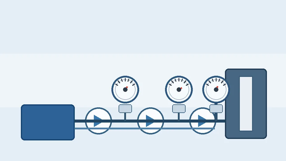
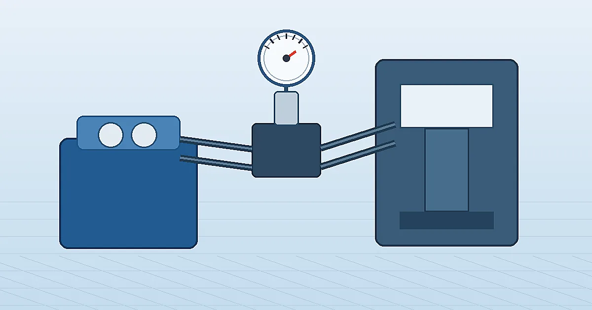
A useful hydraulic system pressure gauge is placed where the reading supports a real decision. Common points include pump outlet pressure, pressure-reducing valve outlet, accumulator charging line, filter differential pressure, manifold test port and actuator work line. A gauge located far downstream of a valve may be easy to see but poor for diagnosing pump output. A gauge installed directly on a vibrating pump body may fail early even if the range is correct.
| Measurement point | What the reading helps judge | Typical gauge choice |
|---|---|---|
| Pump outlet or main pressure line | Pump output, relief setting, pressure spikes, system baseline | Liquid-filled Bourdon gauge, snubber if pulsation is severe |
| Manifold test port | Valve setting, local troubleshooting, commissioning | Compact hydraulic gauge with matching test coupling |
| Accumulator line | Charge/discharge behavior and isolation checks | Gauge rated above maximum system pressure with isolation valve |
| Filter inlet/outlet | Element loading and bypass risk | Differential pressure gauge or paired local gauges |
Choose range for normal pressure, relief pressure and spikes
Gauge range selection starts with four numbers: normal working pressure, maximum relief-valve setting, expected pressure spike and proof or test pressure required by the machine builder. Many hydraulic machines use gauges in the 100 bar, 160 bar, 250 bar, 400 bar or 600 bar families, but the nameplate pressure alone is not enough. The normal reading should sit in the readable middle portion of the dial while leaving margin for short overpressure events.
For steady service, a common target is to keep normal pressure roughly between 25% and 75% of full scale. For strong pulsation or surge, choose more margin and consider overpressure protection, a restrictor, a snubber or a transmitter designed for dynamic pressure. Final selection must follow the hydraulic schematic, maximum allowable pressure, hose and fitting ratings, local safety rules and the machine OEM specification.
Prepare a Hydraulic Gauge RFQ Checklist →Our engineers respond within 24 hours→Liquid-filled gauges, snubbers and stainless wetted parts

A liquid-filled pressure gauge is often the practical default for hydraulic power units because glycerine or silicone fill damps pointer flutter and reduces movement wear. Dry gauges can work on clean, stable test panels, but they are more vulnerable to vibration and unreadable pointer oscillation. Stainless steel wetted parts are preferred where water-glycol fluids, outdoor equipment, washdown, corrosion risk or long service life are important.
A snubber or restrictor slows the pressure reaching the sensing element. It can protect the gauge from pump ripple and valve shock, but it also slows response. That tradeoff matters during commissioning: a heavily restricted gauge may hide the short pressure event the technician needs to see. For dirty oil, confirm that the orifice will not plug. For hot circuits, confirm the case fill, seal materials and ambient temperature limits.
Installation details for presses, power units and manifolds
Install the gauge so it can be read, isolated, bled and replaced without disturbing the machine. Use an isolation valve or test coupling where maintenance requires removal. Support the gauge or use a short remote line when pump vibration is high. Match NPT, BSP, G or metric threads before installation, and avoid forcing unlike thread forms. Where operators stand near the gauge, consider a safety-pattern case or remote mounting for high-pressure service.
- Confirm the pressure tap against the hydraulic schematic, not only the closest free port.
- Keep impulse lines short and protected from mechanical damage.
- Use compatible sealing materials for mineral oil, water-glycol or fire-resistant fluids.
- Record baseline pressure at the same oil temperature, pump speed and valve state.
Risk boundaries: what a hydraulic gauge cannot prove
A hydraulic pressure gauge does not prove flow rate, oil cleanliness, actuator force, accumulator precharge or valve condition by itself. It cannot show a millisecond pressure spike if the gauge movement and snubber are too slow. It also cannot make an underspecified hose, fitting or manifold safe. A normal pressure reading can still hide low flow, aerated oil, thermal drift, internal leakage or a blocked return path.
For presses, lifting equipment, hazardous motion, high pressure above common catalogue ranges, fire-resistant fluids, oxygen-adjacent systems or explosion-risk areas, treat this guide as a selection aid only. Confirm pressure rating, burst protection, material compatibility, standards, guarding and test procedures with the machine builder and site engineer before ordering. Manogauge can support pressure gauge selection from Zhejiang manufacturing resources, but final suitability belongs to the project specification.
Hydraulic pressure gauge selection checklist
Before sending an RFQ, collect the hydraulic circuit function, normal pressure, relief setting, possible spike pressure, fluid type, oil temperature, pulsation level, vibration level, connection thread, mounting position, dial diameter, accuracy class, case material, wetted material, filling liquid and whether a snubber, isolation valve or test coupling is required. Include photos or a schematic when possible.
In short, hydraulic pressure gauge selection works best when the gauge is chosen as part of a diagnostic point, not as a generic accessory screwed into the nearest port.
Related products
- Liquid-Filled Pressure Gauge - Radial (ZX-06-R) — 0–60 MPa
- Shock-Resistant Pressure Gauge - Radial (ZX-03-R) — 0–270 psi
- Stainless Steel Pressure Gauge - Radial (ZX-01-R) — 0–100 MPa
Frequently asked questions
What pressure range should a hydraulic pressure gauge use?
Start from normal working pressure, relief-valve setting and possible pressure spikes. Keep normal pressure in the readable middle of the dial while leaving enough margin for surge and OEM safety limits.
Are liquid-filled gauges better for hydraulic systems?
Usually yes when vibration or pump pulsation is present. Liquid fill damps pointer flutter and movement wear, but temperature, fill fluid and response speed still need confirmation.
When does a hydraulic gauge need a snubber?
Use a snubber or restrictor when pump ripple or valve shock causes pointer flutter or early failure. Avoid excessive restriction when fast pressure events must be visible.
Can a pressure gauge prove hydraulic flow?
No. Pressure helps diagnose circuit condition, but flow requires a flow meter or machine data. Normal pressure can still hide leakage, low flow or a blocked return path.
Which connection is common for hydraulic pressure gauges?
NPT, BSP, G and metric threads are all used. Match the actual port or test coupling before installation and never force unlike thread forms.