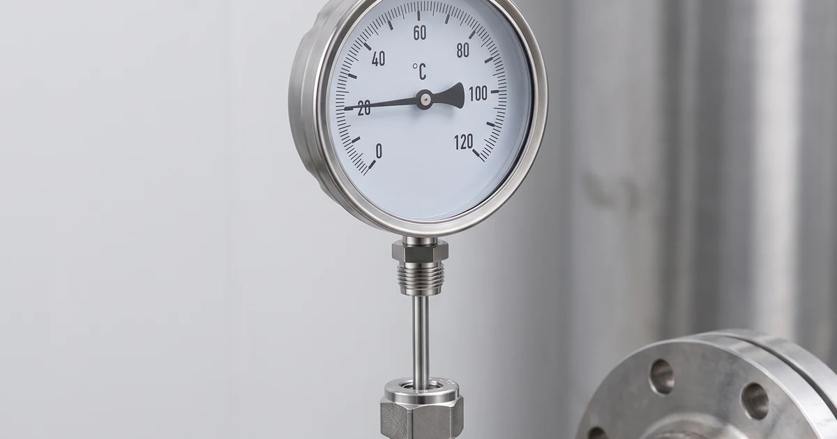
Bimetal thermometer thermowell selection starts with a simple maintenance question: can the thermometer be removed, calibrated or replaced without opening a hot, pressurised or contaminated process line? Answering it well means fixing four things together - insertion length, wetted material, process connection and mechanical strength in the flow - because a dial that is correct on paper can still read the pipe wall instead of the medium, respond too slowly to be useful, or fail a wake-frequency check on a high-velocity steam line. This guide works through each decision, with worked insertion-length examples, a material and service table, the process data a supplier needs for a vibration check, and an RFQ checklist for steam, hot water, thermal oil and utility service.
What a thermowell changes in bimetal thermometer selection
Bimetal thermometer thermowell selection is not only an accessory decision. A thermowell is a pressure-retaining pocket installed in the pipe or vessel. The thermometer stem slides into that pocket, so the sensing element sees process temperature through the metal wall instead of contacting the medium directly.
That separation solves three practical problems: the thermometer can be removed while the line remains closed, the stem is protected from corrosion or erosion, and the plant can standardise one process connection while using different dial ranges. The tradeoff is response time. A bare stem responds faster; a heavy thermowell responds slower but is safer in steam, hot water, thermal oil and contaminated services.
For Manogauge ZX-14 bimetal thermometers, start with the visible indication requirement, then confirm the thermowell. Useful linked references include the bimetal thermometer product page and the broader stainless steel thermometer option for corrosive utility areas.
Compare Bimetal Thermometer OptionsCheck dial size, range, stem and connection options→Bimetal thermometer thermowell selection for insertion length
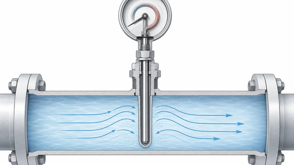
The sensing section must reach a representative part of the flow. If the tip sits in a stagnant branch, close to a pipe wall, or inside a short boss, the dial may look stable while reading a biased temperature. As a starting rule, place the tip near the centre third of the pipe for liquid service when mechanical strength allows it, and use an elbow installation when a small pipe cannot accept enough straight insertion length.
Insertion length depends on pipe size, insulation thickness, nozzle height, thermowell style and thermometer stem length. A long thermowell improves exposure but increases bending load and wake-frequency risk. A short thermowell is stronger but may under-read or over-read when the pipe wall is hotter or colder than the flowing medium.
Do not specify only the dial range. For a correct RFQ, include pipe size, nozzle height, insulation thickness, desired visible dial position, stem diameter, connection thread and whether the thermometer must be removable during operation.
Insertion length worked examples
Insertion length is where most thermowell RFQs go wrong, usually because only the pipe size was considered. The dimension the supplier needs is U, the length from the underside of the process connection to the tip, and it has to absorb three separate distances: the insulation thickness, the nozzle or standoff height, and the immersion into the flowing medium.
Manufacturers do not all measure U from the same datum - some from the flange face, some from the thread shoulder - and the lagging extension is often quoted as a separate dimension T. Confirm the datum on the drawing before releasing the order; a 40 mm misunderstanding here is a thermowell that cannot reach the flow.
| Line | Insulation | Nozzle or standoff | Immersion target | Required U | Standard length to order |
|---|---|---|---|---|---|
| DN50 hot water | 40 mm | 75 mm | about 30 mm, tip past the boundary layer | 40 + 75 + 30 = 145 mm | 150 mm, verify tip clearance in the bore |
| DN100 steam header | 50 mm | 100 mm | about 55 mm, tip near the centre third | 50 + 100 + 55 = 205 mm | 250 mm, or 200 mm if the wake-frequency check allows |
| DN200 thermal oil | 60 mm | 100 mm | about 90 mm, tip near the centre third | 60 + 100 + 90 = 250 mm | 250 mm; check unsupported length against velocity |
| DN25 branch | 30 mm | 60 mm | Cannot reach representative flow radially | Install in an elbow, facing the flow | 100-150 mm along the pipe axis rather than across it |
Then check the thermometer against the well rather than against the pipe. The stem must be long enough to reach the bottom of the bore, because a stem shorter than the bore leaves an air gap at the tip that both slows the response and biases the reading toward the stem temperature. Stem diameter must match the bore, and the dial orientation has to leave the face readable from where the operator actually stands.
Small lines are the hardest case. When a radial installation cannot give representative immersion, an elbow installation with the tip facing into the flow is usually better than accepting a short insertion, and the wake-frequency question then has to be re-examined for the new orientation.
Send Thermowell Application DataInclude medium, temperature, pressure, velocity and connection→Material, connection and process compatibility
Material choice should follow the medium, temperature and cleaning chemistry. 304 stainless steel is common for clean hot water and utility steam. 316L stainless steel is the safer default for condensate, treated water, many chemical utilities and outdoor washdown areas. Brass stems are economical in mild service but should not be used where dezincification, ammonia, strong cleaning chemicals or sanitary expectations are present.
| Service | Typical concern | Thermowell selection focus |
|---|---|---|
| Steam and condensate | High temperature, pressure and water hammer | Stainless thermowell, sealed thread or flange, enough lagging extension |
| Thermal oil | High temperature and oxidation deposits | Material rated for oil temperature, removable thermometer, conservative insertion length |
| Food or CIP utilities | Cleaning chemicals and hygiene expectations | 316L wetted material, sanitary connection if product-contact, avoid crevices |
| HVAC hot water | Corrosion inhibitors and low flow periods | Stainless or brass only when compatible, dial visible from walkway |
Threaded connections are compact and cost-effective. Flanged or welded connections are preferred when pressure class, plant standard or maintenance policy requires a fixed pressure boundary. Match NPT, BSP, G or metric threads deliberately; a nearly fitting thread is not a safe seal.
Wake-frequency and vibration checks for thermowells
A thermowell is a small cantilever in the flow. At sufficient velocity, vortices shed from the thermowell and create cyclic forces. If those forces approach the thermowell natural frequency, fatigue can damage the well, the process nozzle or the thermometer. This is why high-velocity steam, gas and light-liquid lines need more than a dimensional sketch.
The external reference most commonly used for this check is ASME PTC 19.3 TW. WIKA notes that wake-frequency calculation in accordance with ASME PTC 19.3 TW-2016 is used to evaluate thermometer thermowells. In practical RFQs, the supplier cannot run that check without process data: medium, density, pressure, temperature, velocity or flow rate, pipe size, thermowell profile and unsupported length.
When the calculation is unfavourable, the fix is usually engineering rather than guesswork: shorten the unsupported length, increase root diameter, use a tapered profile, move to an elbow, reduce velocity at the measurement point, or select a different measurement technology.
Response time: what actually slows a thermowell down

Every thermowell trades response speed for pressure retention and mechanical protection. That trade is acceptable on a slowly varying utility line and unacceptable where the reading is used to judge a transient, so it is worth knowing which parts of the assembly dominate the delay. In practice the largest single contributor is usually the annular air gap between the stem and the bore, not the thickness of the well wall.
| Factor | Effect on response | Practical mitigation |
|---|---|---|
| Annular gap between stem and bore | Air is a poor conductor; a loose fit can dominate the total delay | Specify the bore tolerance, or use a spring-loaded stem that holds contact at the tip |
| Tip contact and bore bottom form | A stem that does not reach the bottom measures a pocket of air | Match stem length to bore depth and confirm the tip form on the drawing |
| Well wall thickness and profile | Heavier walls add thermal mass; straight wells are slower than tapered | Use a tapered or stepped profile where strength allows |
| Velocity at the tip | Low velocity gives a poor film coefficient and a sluggish, biased reading | Place the tip in the flowing section, not in a dead leg or a stagnant branch |
| Conduction along the stem | Heat leaks to the cooler connection and the reading is pulled toward ambient | Increase immersion and insulate the nozzle rather than the dial case |
| Insulation and radiant heat around the dial | A warm or wrapped case shifts the indication independently of the process | Leave the case clear; use a lagging extension for the insulated section |
| Heat-transfer paste or oil in the bore | Fills the gap and speeds response noticeably | Only where the temperature limit, migration and cleaning rules allow; confirm with the plant |
One boundary is worth stating plainly: catalogue response-time figures are measured in a defined test - typically a step change into water or air at a stated velocity - and cannot be transferred to a different medium, velocity or well geometry. If the response time genuinely matters to the control or safety function, that function should not be based on a local bimetal dial in a heavy thermowell in the first place.
What a bimetal thermometer cannot prove
A local bimetal thermometer is useful because it is visible, self-powered and easy to verify during rounds. It does not prove the control-loop temperature, batch record temperature or safety interlock value unless it is installed at the same representative point and maintained under the same calibration plan.
Several errors are common: installing the thermowell after a dead leg, using a stem shorter than the thermowell bore, wrapping insulation around the dial case, placing the dial where radiant heat from a boiler front warms the case, or assuming a slow-moving thermal oil line has the same response as a turbulent water line. These are installation and process errors, not thermometer accuracy errors.
For critical boilers, fired heaters, pressure vessels, sanitary product contact, hazardous areas or high-pressure steam, this guide is only a selection reference. The final design should be confirmed by the plant engineer, vessel/nozzle designer and any applicable site standard.
RFQ checklist for bimetal thermometer thermowell selection
Before requesting a quote, collect the data that determines fit and risk. Send the normal and maximum temperature, pressure, medium, pipe size, flow velocity or flow rate, connection standard, insertion length target, insulation thickness, dial diameter, mounting orientation and any cleaning or corrosion concerns.
For Manogauge, also specify whether the target is an economical utility thermometer, a stainless steel outdoor unit, a sanitary-style assembly, or a removable thermometer for thermal oil or steam service. A complete checklist reduces back-and-forth and helps avoid the common mismatch where the dial looks correct but the stem, connection or thermowell cannot fit the process.
In short, bimetal thermometer thermowell selection should balance readable local indication, safe pressure retention, representative insertion length and verified mechanical strength.
Related guides: industrial pressure gauge selection guide and steam pressure gauge siphon selection cover companion instrumentation for the same process loops.
For bimetal thermometer supply with standard and custom thermowell configurations, see Manogauge's bimetal thermometer manufacturer page for process, steam and HVAC temperature loops.
Key takeaways
- A thermowell improves maintenance safety and lets the thermometer be removed on a live line, but it slows temperature response.
- Insertion length U is the sum of insulation, nozzle standoff and immersion, and must be reconciled with mechanical strength and the manufacturer's measuring datum.
- High-velocity steam, gas and light-liquid service needs real process data for an ASME PTC 19.3 TW style wake-frequency and vibration check.
- A local bimetal dial cannot prove a control-loop, batch-record or interlock temperature, and catalogue response times do not transfer to a different medium or geometry.
Related buyer pages
Bimetal thermometer manufacturerStem length, insertion depth, thread and dial size confirmed against the thermowell.
Custom pressure gauge manufacturerCustom stem lengths, C/F ranges and OEM dial printing for instrument packages.
Stainless steel pressure gauge manufacturerMatch the pressure points on the same line with 304/316L stainless gauges.
Related reading
- District Heating Pressure Gauge: How to Pick Range and Temp
Pressure gauges for a district heating substation: primary vs secondary loop ranges, strainer DP points, hot-water temperature limits and siphon checks.
- 316L vs Brass Pressure Gauge Wetted Parts: Corrosion Guide
316L vs brass pressure gauge wetted parts compared for corrosion risk in water, steam, ammonia, seawater, chlorides, CIP/SIP cleaning and diaphragm seals.
- A2L R-454B Refrigerant Pressure Gauge Selection
A2L R-454B refrigerant pressure gauge selection for HVAC service: manifold gauge use, PT chart checks, service ports, gauge range and safe workflow.
- Sanitary Pressure Gauge for Food & Pharma
Sanitary pressure gauge selection for CIP/SIP dairy, beverage and biopharma lines: 3-A and EHEDG scope, FDA wetted materials and tri-clamp connections.
- Pressure Gauge Failure Modes: Diagnosis & Repair
Pressure gauge failure modes and troubleshooting: stuck pointer, zero drift, flutter, fogging, sluggish response and overpressure damage, with root causes.
Frequently asked questions
When is a thermowell required for a bimetal thermometer?
Use a thermowell when the line is pressurised, hot, corrosive, contaminated, or must stay closed while the thermometer is removed. Bare-stem installation is usually limited to low-risk tanks, ducts or non-pressurised service.
What data is needed for a thermowell wake-frequency check?
Provide medium, density, temperature, pressure, velocity or flow rate, pipe size, thermowell profile, material, root diameter and unsupported insertion length. Without those data, ASME PTC 19.3 TW-style evaluation cannot be meaningful.
How deep should a bimetal thermometer thermowell be inserted?
The sensing section should reach representative flow, often near the centre third of a liquid pipe when strength allows. Small pipes may need elbow installation or a reduced insertion length verified against expected response error.
Can one bimetal thermometer fit any thermowell?
No. Stem diameter, stem length, thread, lagging extension, tip clearance and dial orientation must match the thermowell bore and process connection. A wrong fit can slow response or prevent full insertion.
Is 316L stainless steel always required?
No. 316L is a conservative choice for corrosion, condensate and washdown, but clean HVAC water may allow brass or 304 stainless steel if compatible. Confirm medium chemistry, cleaning fluid and site standards before choosing.
How is thermowell insertion length U calculated for a bimetal thermometer?
Add the insulation thickness, the nozzle or standoff height and the immersion needed to reach representative flow, then round up to the nearest standard length and verify the result against the wake-frequency check. For example, a DN100 line with 50 mm insulation, a 100 mm standoff and 55 mm of immersion needs about 205 mm, so a 250 mm well is ordered. Confirm which datum the manufacturer measures U from, because conventions differ.
Why does a bimetal thermometer read low even with the correct thermowell?
The usual causes are installation rather than instrument accuracy: too little immersion so heat conducts along the stem to the cooler connection, a stem that does not reach the bottom of the bore leaving an air gap at the tip, a tip sitting in a dead leg or against the pipe wall, or an uninsulated nozzle on a hot line. Check immersion, stem-to-bore fit and nozzle insulation before questioning the dial.
Can heat-transfer paste be used inside a thermowell?
Sometimes, and it can noticeably improve response by filling the annular gap. The limits are the paste's temperature rating, migration or degradation over time, and whether the service permits it at all - many food, pharmaceutical and cleanliness-controlled applications do not. Confirm the paste specification with the plant and the thermowell manufacturer rather than treating it as a default fix.