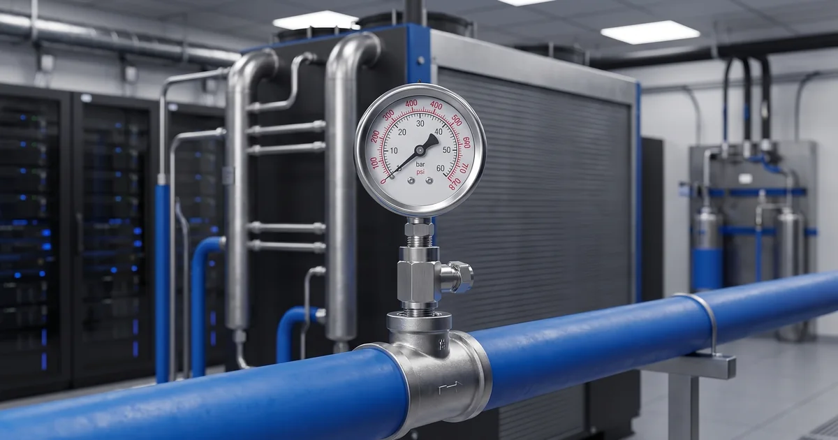
AI data center liquid cooling pressure monitoring has become a practical requirement as GPU clusters push rack power density beyond what traditional air cooling can handle. In direct-to-chip and CDU-based loops, pressure is not just a number on a dial: it confirms pump discharge, supply and return stability, rack manifold balance, filter loading, and early leak symptoms. This guide explains where mechanical pressure gauges, differential pressure gauges, and pressure transmitters fit in high-density AI cooling loops, and how buyers can specify suitable wetted materials, ranges, connections, and documentation when sourcing from a China pressure gauge manufacturer such as Manogauge.
Why AI Data Center Liquid Cooling Pressure Monitoring Matters Now
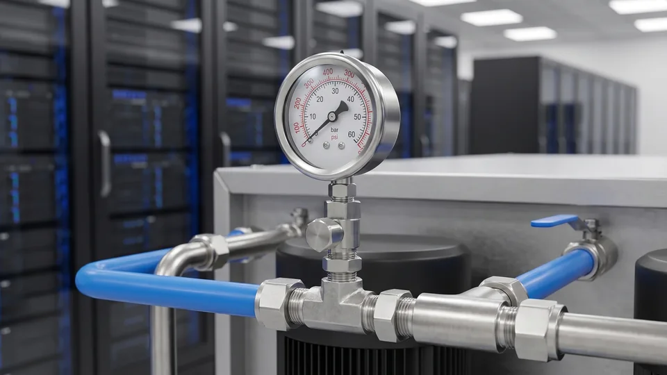
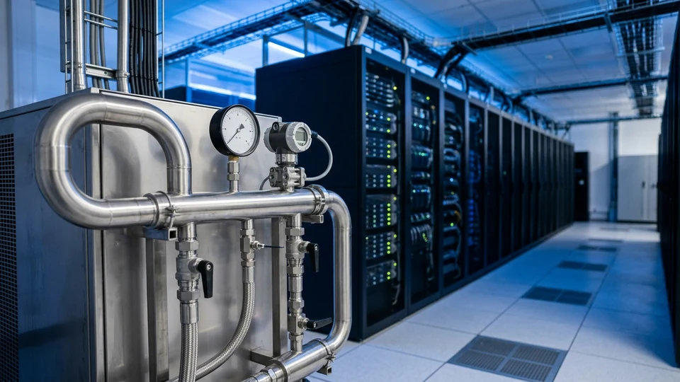
AI training clusters and inference racks are pushing power density higher, so many facilities are moving from air cooling to direct-to-chip liquid cooling, rear-door heat exchangers, immersion cooling, or hybrid systems. In these architectures, the coolant distribution unit (CDU) becomes part of the reliability chain. Stable pressure helps verify that pumps are delivering flow, cold plates are not starved, and rack manifolds are balanced. A local pressure gauge near a CDU or manifold gives maintenance teams a fast visual check, while a pressure transmitter feeds continuous data to BMS, DCIM, or PLC systems for alarms and trend analysis. For exporters and procurement teams, this is also a specification issue: the instrument must match coolant chemistry, operating range, connection thread, mounting position, and documentation requirements before it is approved for a data center project.
For current data-center thermal guidance, consult the ASHRAE Datacom Series.
Browse Our Pressure Gauge CatalogExplore 143+ industrial gauge models→Where Pressure Gauges Fit in CDU, Pump, and Rack Manifold Loops
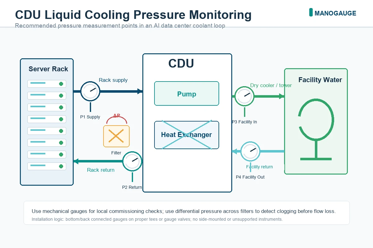
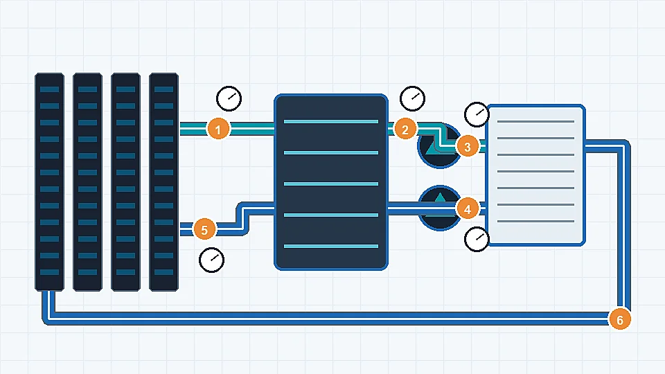
Pressure measurement should be planned around the hydraulic behavior of the liquid cooling loop. CDU supply pressure confirms whether the pump is delivering sufficient head to the rack row. Return pressure helps identify abnormal backpressure or restrictions. Pump discharge gauges are useful during commissioning because they can show cavitation symptoms, blocked valves, or unexpected pressure drop before the electronic system is fully tuned. Rack inlet and outlet manifold points help technicians compare zones and verify whether a specific GPU rack is receiving stable flow. For critical loops, a mechanical gauge and a transmitter are often used together: the gauge supports local inspection, while the transmitter records alarms and historical data.
Filter DP points should be specified with the differential pressure gauge selection guide.
Selecting Coolant Pressure Gauges and Transmitters for AI Data Centers
Instrument selection starts with the coolant. Many data center loops use water-glycol mixtures, but some designs use dielectric fluids or proprietary additives. Wetted parts, seals, and process connections must be confirmed against that exact fluid. Stainless steel wetted parts are often preferred for corrosion resistance, but the final choice should be checked against the coolant supplier and the instrument manufacturer. Buyers should define normal operating pressure, maximum pressure, expected temperature, vibration, accuracy class, dial size, output signal, thread type, and whether calibration records are needed. As a China pressure gauge manufacturer, Manogauge can support mechanical gauges, digital gauges, and pressure-instrument selection discussions, but final specifications must be confirmed against the project’s actual CDU and rack-loop design. For cross-border sourcing, ask for a written confirmation of wetted material, dial marking, pressure range, thread standard, inspection method, and packing method before approving mass production. This helps avoid a common mismatch where the gauge appears suitable in a catalog photo but the connection, seal, or pressure range does not match the CDU manifold.
Coolant compatibility depends on wetted material; compare 316L stainless steel vs. brass wetted parts compatibility.
Request a Free QuoteOur engineers respond within 24 hours→The cold plate sets the pressure ceiling, not the pump
A recurring specification error in direct-to-chip projects is to size instruments and protection from the CDU pump curve. In a technology cooling loop the allowable pressure is set by the weakest element in the secondary circuit, which is usually the cold plate, the quick-disconnect couplings or a flexible hose - not by what the pump can produce against a closed system. The gauge range, the overpressure rating and any relief arrangement all have to be selected against that ceiling.
Build the pressure map from documents rather than from assumptions. Every element below has a published limit somewhere in the CDU, cold-plate or rack documentation, and the instrument specification should quote where each number came from.
| Loop element | What limits pressure there | Where the number comes from | Instrument consequence |
|---|---|---|---|
| Cold plate | Maximum operating pressure of the plate and its seals | Cold-plate or server vendor datasheet | Usually the lowest ceiling in the loop; sets the alarm setpoint |
| Quick-disconnect couplings | Rated working pressure, and rating when disconnected | Coupling manufacturer datasheet | A rack-level limit that is easy to overlook during a retrofit |
| Rack manifold and flexible hoses | Hose pressure rating at the operating temperature | Hose and manifold datasheets | Ratings fall with temperature; check at the hot return, not at ambient |
| CDU secondary pump | Dead-head head with all rack valves closed | CDU pump curve in the CDU manual | Sets the worst-case pressure the gauge must survive without damage |
| Static head in tall or multi-floor layouts | Height between the CDU and the highest or lowest connection | Project piping drawing | Shifts the whole operating band; matters for range selection |
| Filter or strainer | Element collapse pressure at maximum DP | Filter element datasheet | Defines the DP alarm ceiling, not just the cleaning setpoint |
| Expansion tank and relief | Precharge and relief setting | CDU manual and commissioning record | Explains the normal pressure band and how much it moves with temperature |
Where a number is not published, ask for it in writing before the instrument is fixed. General guidance such as the ASHRAE datacom series and open design references describe the architecture, but they do not carry the pressure limits of the specific cold plate and couplings on your project, and those limits are what the gauge has to respect.
Using Differential Pressure to Detect Filter Loading and Flow Restriction
Differential pressure monitoring is one of the most useful maintenance signals in a liquid cooling system. A filter may look normal from the outside while debris gradually increases pressure drop across the element. A differential pressure gauge or transmitter across the filter gives operators a measurable trigger for cleaning or replacement. The same method can be applied across heat exchangers, coolant strainers, or selected manifold sections to detect fouling and flow restriction. For AI data centers, this matters because poor coolant distribution can quickly turn into thermal throttling, equipment shutdown, or unplanned service windows.
Facility teams can map these locations against BICSI 002 data center design practices.
Pressure-decay leak checks and why the baseline must be temperature-compensated
A closed liquid cooling loop is a fixed volume of nearly incompressible fluid behind an expansion device, so its pressure responds strongly to coolant temperature. A loop that loses pressure overnight has not necessarily developed a leak; it may simply have cooled down as the IT load dropped. Recording pressure without recording the coolant temperature at the same moment produces both false alarms and missed leaks.
The workable method is a compensated baseline: log supply pressure, return pressure and coolant temperature together at a defined load state, and judge later readings against the reading at the same temperature. A drop that tracks a temperature drop is thermal contraction. A drop at constant temperature, with no make-up water added, is a candidate leak and justifies a physical inspection.
| Observation | Most likely cause | Confirming check | What it does not prove |
|---|---|---|---|
| Pressure falls and coolant temperature falls with it | Thermal contraction after a load drop | Compare against an earlier reading at the same temperature | That the loop is leak-free |
| Pressure falls at constant temperature and load | Candidate leak, or expansion-tank precharge loss | Isolate sections; check tank precharge; inspect with leak detection | Where the leak is; decay gives no location |
| Pressure rises at constant temperature | Gas ingress, make-up valve passing, or a blocked expansion path | Check make-up isolation and vent the high points | That flow is adequate |
| Filter DP rises while supply pressure is stable | Element loading | Compare with the clean-element DP at the same flow | Which contaminant is loading the element |
| Supply pressure normal but a rack runs hot | Flow maldistribution or a partially closed branch | Compare rack inlet and outlet manifold readings across zones | Cold-plate condition or thermal-interface problems |
Resolution matters as much as method. A wide-range dial cannot show the small decay that makes this test useful, so either fit a gauge whose span suits the operating band or take the decay reading from a transmitter logged by the BMS. Above all, treat decay as a screening signal: it cannot locate a leak, it cannot see a leak smaller than the make-up system quietly replaces, and it does not replace rack-level leak detection, drip trays or liquid-detection cable. For the mechanical side of getting a trustworthy reading, see pressure gauge installation best practices and the pressure transmitter versus pressure gauge comparison.
RFQ Checklist for Global Buyers Sourcing Data Center Cooling Instruments
Before issuing an RFQ for AI data center liquid cooling pressure monitoring, buyers should provide the coolant type, pressure range, maximum temperature, connection thread, required dial diameter, installation position, ingress protection needs, output signal, alarm requirements, and quantity. If the project requires export packing, private label, calibration documentation, sample approval, or staged delivery, these should be stated early. Avoid selecting a gauge only by appearance; the same dial style can be unsuitable if the wetted material, seal, pressure range, or thread is wrong. For high-density data center projects, the safest workflow is to send the CDU or piping drawing, confirm the instrument specification with the manufacturer, test samples where possible, and then approve production. Buyers serving North America, Europe, Southeast Asia, or the Middle East should also clarify label language, carton marks, spare quantity, and whether the shipment is for pilot installation or long-term maintenance stock. These details improve RFQ accuracy and make the page useful for both search engines and AI answer engines looking for concrete procurement criteria.
Commissioning and service checks should follow pressure gauge installation best practices.
For local digital readout or 4–20 mA output in precision cooling loops, Manogauge's digital pressure gauge supplier page covers models with configurable alarm and display output.
Key takeaways
- AI data center liquid cooling pressure monitoring should cover CDU supply and return, pump discharge, rack manifolds, filters and heat exchangers.
- The pressure ceiling comes from the weakest element in the secondary loop - usually the cold plate or a quick-disconnect coupling - not from the CDU pump curve.
- Mechanical gauges give local commissioning visibility while transmitters provide BMS and DCIM alarms, trend data and the resolution needed for decay checks.
- Differential pressure across filters and heat exchangers turns pressure data into a maintenance trigger for clogging, fouling and flow restriction.
- Pressure decay is a screening signal against a temperature-compensated baseline; it cannot locate a leak or replace rack-level leak detection.
Related buyer pages
Digital pressure gauge supplierDigital gauges with fine resolution for CDU loops and low-pressure coolant circuits.
Stainless steel pressure gauge manufacturer316L wetted parts compatible with treated water and glycol coolant chemistry.
Bimetal thermometer manufacturerSupply and return coolant temperature points with thermowells on the same skid.
Related products
- Liquid-Filled Pressure Gauge - Radial (ZX-06-R) — 0–60 MPa
- Stainless Steel Pressure Gauge - Radial (ZX-01-R) — 0–100 MPa
Related reading
- Cooling Tower Pressure Gauge Monitoring Guide
Cooling tower pressure gauge monitoring for condenser water loops: gauge points, strainer DP, side-stream filters, materials and range selection.
- Hydrogen Electrolyzer Pressure Monitoring: Selection Guide
Hydrogen electrolyzer pressure monitoring guide for hydrogen, oxygen and water loops: instrument type, isolation, materials, alarms and safety limits.
- Industrial Heat Pump Pressure Monitoring Guide
Industrial heat pump pressure monitoring for retrofits: gauge and transmitter selection, range, materials, installation points and commissioning checks.
- Dry vs Liquid-Filled Pressure Gauges: Fill and Vibration Guide
Dry vs liquid-filled pressure gauge guide comparing glycerin, silicone oil and dry case designs for vibration, pulsation, temperature and maintenance risk.
- How to Select an Industrial Pressure Gauge: 8-Step Guide
Select the right industrial pressure gauge in 8 steps: range and span, wetted materials, element type, accuracy class, dial size, threads and case rating.
Frequently asked questions
What is AI data center liquid cooling pressure monitoring?
AI data center liquid cooling pressure monitoring means measuring pressure at CDU supply and return lines, pump discharge, rack manifolds, filters, and heat exchangers so operators can verify flow stability, detect restrictions, and respond to leak or pump problems before they affect GPU cooling.
Where should a coolant pressure gauge be installed in a CDU loop?
Common locations include CDU supply and return headers, pump discharge, rack inlet/outlet manifolds, and service points near filters or heat exchangers. The final location should follow the CDU piping drawing and the data center maintenance workflow.
Should a data center use mechanical gauges or pressure transmitters?
Both are useful. Mechanical gauges provide local visual confirmation during commissioning and maintenance, while pressure transmitters send continuous data to BMS, DCIM, PLC, or alarm systems. Critical loops often use both.
Which wetted material is suitable for liquid cooling pressure instruments?
The correct wetted material depends on the coolant. Stainless steel is commonly selected for corrosion resistance in water-glycol systems, but compatibility must be confirmed with the coolant supplier and instrument manufacturer, including seals and thread materials.
What should overseas buyers include in an RFQ for cooling-loop gauges?
Include coolant type, pressure range, maximum temperature, connection thread, dial size, accuracy, output signal if needed, installation drawings, calibration or documentation needs, quantity, packaging, branding requirements, and target delivery schedule.
What pressure range should a CDU secondary-loop gauge have?
Size it from the loop's design ceiling rather than from the pump duty point. The ceiling is normally the lowest rated element in the secondary circuit, often the cold plate or a quick-disconnect coupling, and the worst-case pressure is the CDU pump dead-head with rack valves closed. Add static head for tall or multi-floor layouts, then choose a span that keeps normal running in the middle of the dial while covering the worst case.
Can a pressure gauge detect a leak in a direct-to-chip loop?
Only as a screening signal, and only against a temperature-compensated baseline. Loop pressure moves with coolant temperature, so an overnight drop may be thermal rather than a leak. Pressure decay also cannot locate a leak and cannot see one small enough for the make-up system to replace, so it supplements rather than replaces rack-level leak detection, drip trays and liquid-detection cable.
Why does liquid cooling loop pressure change overnight with no leak?
Because the loop is a closed, nearly incompressible volume behind an expansion tank. When IT load falls, coolant temperature falls, the fluid contracts and pressure drops; when load returns, pressure rises again. Log coolant temperature alongside pressure and compare readings taken at the same temperature, otherwise normal thermal behaviour is easily mistaken for a fault.