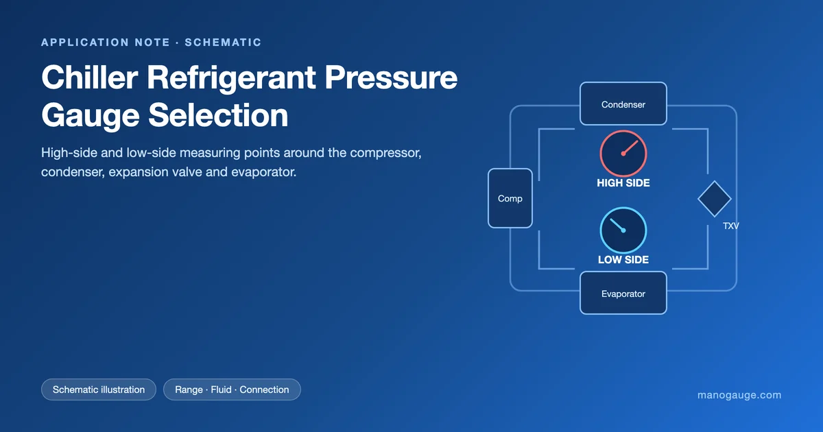
Chiller refrigerant pressure gauges are not interchangeable with standard industrial gauges. Each refrigerant circuit — high-side discharge, low-side suction, and maintenance vacuum — demands a different pressure range, Bourdon tube material, and connection standard. This guide covers gauge selection for R-22, R-134a, R-410A, R-407C, and CO2 (R-744) chiller systems, with decision points for range, accuracy class, and wetted materials.
Refrigerant pressure ranges chillers actually require
Chiller refrigerant pressure gauges must match the saturation curve of each refrigerant. The table below gives the typical high-side and low-side pressures at common operating conditions:
| Refrigerant | High-side (condensing, 45°C) | Low-side (evaporating, 5°C) | Recommended gauge range |
|---|---|---|---|
| R-22 | ~17 bar (246 psi) | ~5.8 bar (84 psi) | High: 0–25 bar | Low: 0–10 bar or compound |
| R-134a | ~11.6 bar (168 psi) | ~3.5 bar (51 psi) | High: 0–16 bar | Low: compound –1 to 10 bar |
| R-410A | ~27.3 bar (396 psi) | ~9.4 bar (136 psi) | High: 0–40 bar | Low: 0–16 bar or compound |
| R-407C | ~17.5-19.7 bar (254-286 psi) | ~5.5-6.7 bar (80-97 psi) | High: 0–25 bar | Low: 0–10 bar |
| CO2 (R-744) | Up to 130 bar (1885 psi) | ~39.7 bar (576 psi) | High: 0–160 bar SS | Low: 0–60 bar SS |
A gauge sized at 130–150% of maximum operating pressure gives the best accuracy across normal working range while protecting the Bourdon tube from pressure spikes.
Read the table as absolute saturation pressure. A gauge on the machine reads roughly 1 bar (14.5 psi) less, because it measures against atmospheric pressure. R-407C is a zeotropic blend with temperature glide, so its saturation pressure is a bubble-point/dew-point band rather than a single value — the discharge gauge sits nearer the bubble point and the suction gauge nearer the dew point. Values calculated from reference equations of state; confirm against the chiller manufacturer's own P–T data before you set alarm points.
High-side chiller gauge selection — discharge pressure monitoring
The high-pressure side of a chiller refrigerant circuit is where the compressor discharges hot gas into the condenser. Key selection criteria:
- Pressure range: For R-410A the discharge can reach 40–45 bar under high ambient conditions. Specify a 0–60 bar gauge (not 0–40 bar) so the pointer stays in the upper third of the dial during normal operation.
- Bourdon tube material: Copper-alloy (brass) Bourdon tubes are standard for HCFC/HFC refrigerants and acceptable for low-pressure CO2. Stainless steel 316L is mandatory for CO2 systems and preferred where cross-contamination from compressor oils or dessicant particles is possible.
- Connection: SAE 1/4" flare is the HVAC refrigerant standard. NPT 1/4" or 1/8" male are typical for fixed panel gauges. Confirm with your service valve port thread before ordering.
- Accuracy class: ASME B40.100 Class 2.5 (±2.5% FS) is sufficient for field service. Fixed machine panel gauges should be Class 1.6 or Class 1.0 for reliable trending.
- Liquid filling: Dry gauges suffice for steady-state high-side monitoring. Liquid-filled (glycerine) gauges are specified when the machine room has high vibration or pulsation from reciprocating compressors.
Low-side and compound chiller gauges — suction circuit and vacuum
The chiller refrigerant low pressure gauge monitors the evaporator side where refrigerant boils at low temperature and pressure. Sub-atmospheric pressures occur during pump-down and commissioning:
- Compound gauge (−1 to +24 bar / −30 inHg to +350 psi): Most versatile for HVAC service work. Reads vacuum on the left (blue) scale and positive pressure on the right. Required when suction pressure can drop below 0 bar absolute (R-134a at low evaporating temperatures).
- Vacuum gauge in Torr or mbar: Used specifically for system evacuation before refrigerant charge. Chiller refrigerant torr gauges must resolve to at least 50 microns (0.05 Torr) to confirm deep vacuum for moisture removal. Thermocouple or Pirani vacuum gauges are used for this, not Bourdon tube gauges, which cannot resolve below ~25 mbar reliably.
- Low-side pressure gauge range: For typical HFC chillers, a 0–16 bar gauge covers normal evaporator pressure, but if pump-down creates vacuum, a compound gauge (−1 to +10 bar) is preferred.
For CO2 systems the low-side operating pressure at +5°C evaporating is already ~27 bar, so a low-side gauge rated to at least 40 bar is required — a standard HVAC compound gauge is completely undersized.
CO2 (R-744) chiller refrigerant gauge requirements
CO2 refrigeration operates at pressures 5–8× higher than HFCs. A standard HVAC manifold gauge set is dangerous on a CO2 chiller. Requirements:
- High-side operating pressure: 80–130 bar in subcritical mode; up to 130+ bar in transcritical systems.
- Safety factor: Select a gauge with a maximum scale of 160 bar and a case burst pressure ≥ 4× the dial maximum. Glycerine filling is strongly recommended to absorb pressure peaks.
- Bourdon tube: Stainless steel 316L tube and socket. Copper alloy is not resistant to CO2 at high pressure and elevated temperature.
- Connection: 1/4" NPT or 1/4" BSP depending on system country of manufacture; confirm CO2-rated valve fittings.
- Certifications: EN 837-1 for European installations; ASME B40.100 for North American systems. CE-marked glycerine-filled stainless steel gauges cover both.
Manogauge supplies stainless steel CO2 refrigerant pressure gauges in 0–100, 0–160, and 0–250 bar ranges, with ATEX option for ammonia–CO2 cascade systems.
Get CO2 Pressure Gauge QuoteOur engineers respond within 24 hours→Chiller refrigerant pressure-temperature relationship
Every pressure reading on a chiller is really a temperature reading. In the condenser and the evaporator the refrigerant is saturated — liquid and vapour coexist — so pressure and temperature are locked together by the saturation curve. That is why a technician can hold a surface thermometer against the suction line and predict what the gauge should show, and why a gauge that disagrees with the temperature is telling you something is wrong with the charge, the airflow or the water flow.
Saturation pressure in bar absolute:
| Refrigerant | -10 °C | 0 °C | +5 °C | +20 °C | +35 °C | +45 °C | +55 °C |
|---|---|---|---|---|---|---|---|
| R-22 | 3.55 | 4.98 | 5.84 | 9.10 | 13.55 | 17.29 | 21.75 |
| R-134a | 2.01 | 2.93 | 3.50 | 5.72 | 8.87 | 11.60 | 14.92 |
| R-410A | 5.74 | 8.00 | 9.35 | 14.45 | 21.42 | 27.30 | 34.36 |
| R-407C | 3.20-4.05 | 4.61-5.68 | 5.47-6.66 | 8.80-10.38 | 13.49-15.45 | 17.53-19.72 | 22.45-24.81 |
| CO2 (R-744) | 26.49 | 34.85 | 39.69 | 57.29 | - | - | - |
R-407C is shown as a dew-point to bubble-point band because of its temperature glide. CO2 has a critical point at 31.0 °C and 73.8 bar absolute, so above roughly 31 °C there is no saturation pressure at all — the high side runs transcritical and pressure is set by the gas cooler control, not by a P–T table. That is exactly why a transcritical CO2 high-side gauge must be sized on the control pressure and relief setting rather than on a condensing temperature.
Three practical uses of the P–T relationship at the gauge: convert suction pressure to saturated suction temperature and subtract it from the measured suction line temperature to get superheat; convert discharge pressure to saturated condensing temperature and compare with the leaving condenser water or air temperature to judge fouling; and, on a machine that has been off long enough to equalise, compare the standing pressure with the P–T value at room temperature to screen for non-condensables or a lost charge. See dial size selection for the readability side of this.
Standing pressure, leak checks and chiller system pressure testing
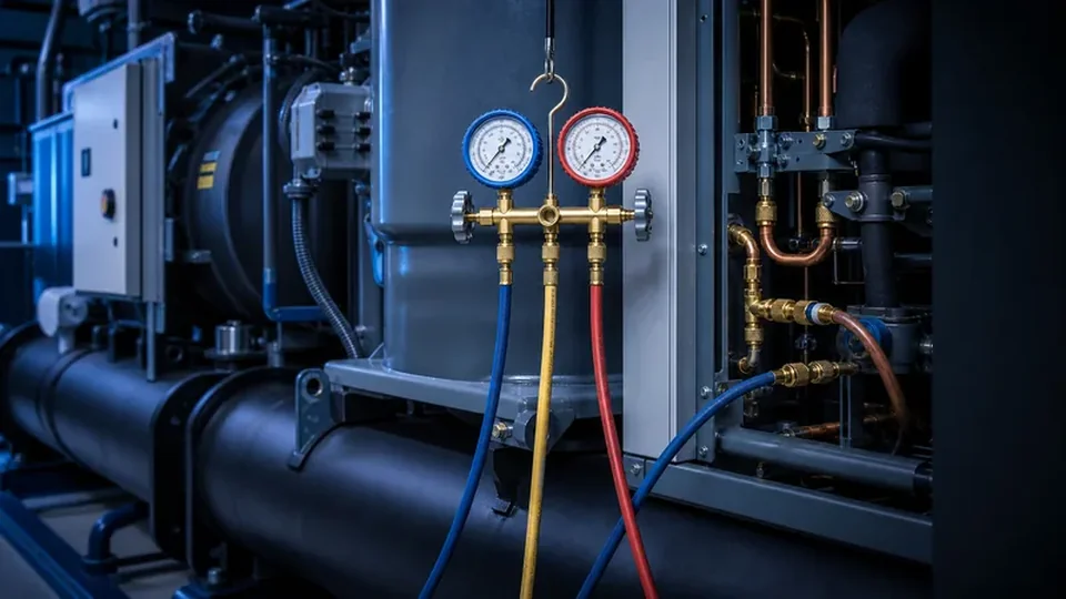
Standing pressure is what the gauges read after the machine has been off long enough for refrigerant and metal to reach the same temperature. On a healthy, correctly charged system both sides settle at the saturation pressure for that refrigerant at the measured ambient or shell temperature, so the standing reading is a free diagnostic: look up the temperature in the P–T table above and compare.
- Standing pressure clearly above the P–T value: usually non-condensables — air or nitrogen left in the circuit after service, or drawn in through a low-side leak that ran in vacuum. The extra partial pressure adds to the refrigerant's saturation pressure.
- Standing pressure clearly below the P–T value: usually an undercharge or a leak that has already emptied part of the circuit. If it reads near zero gauge, treat the system as lost charge, not as a gauge fault.
- Both sides not equalised after hours off: a restriction, a closed service valve or a stuck check valve — not a gauge problem.
- Read it fairly: refrigerant migrates to the coldest component. A machine in a cold plant room, or one where the evaporator still holds chilled water, will not give a clean standing reading until temperatures actually settle.
Pressure testing is a different job and needs a different gauge. Strength and tightness test pressures come from the applicable safety standard — EN 378 in Europe, ASHRAE 15 in North America — together with the equipment nameplate PS/MAWP; they are not a rule of thumb and must never be improvised. Practical gauge requirements for the test itself:
- Test with dry nitrogen (OFN), never with oxygen and never with the system refrigerant as the test medium.
- Use a dedicated test gauge whose full scale is above the test pressure but close enough that the pointer sits in the upper half of the dial — that is where a Bourdon gauge is most readable.
- Specify accuracy class 1.0 or 1.6 for the test gauge. A class 2.5 service gauge cannot resolve the small decay that proves a slow leak over a hold period.
- Correct for ambient temperature change over the hold. Nitrogen in a fixed volume changes pressure roughly 0.3-0.4% per kelvin, so a 5 K swing overnight looks like a leak if you ignore it.
- Do not use the manifold's low-side compound gauge to read a high test pressure, and isolate or remove any gauge whose range is below the test pressure before pressurising.
Evacuation after a successful pressure test is a vacuum measurement, not a pressure measurement — see the torr/micron discussion in the low-side section above. Related reading: overpressure protection and pressure gauge failure modes.
Specifying chiller gauges: materials, connections, and RFQ checklist
When placing an RFQ for chiller refrigerant pressure gauges, provide these parameters to avoid back-and-forth clarification:
- Refrigerant type — R-22, R-134a, R-410A, R-407C, CO2 (R-744), or ammonia (R-717).
- Circuit side — High pressure (discharge/condensing), low pressure (suction/evaporating), or maintenance vacuum.
- Pressure range and unit — bar, psi, or combined with Torr/mbar for vacuum gauges.
- Accuracy class — Field service gauges: 2.5; Panel instruments: 1.6 or 1.0.
- Connection thread and size — SAE flare, 1/4"-18 NPT, 1/4" BSP, or G 1/4".
- Wetted material — Brass (most HFCs), stainless steel 316L (CO2, ammonia).
- Filling — Dry or glycerine-filled.
- Dial size — 40 mm (portable manifolds), 63 mm (service panels), 100 mm (machine room panel).
- Quantity and delivery — MRO stock vs project batch.
Manogauge OEM chiller refrigerant pressure gauges are available as private-label assemblies for HVAC equipment manufacturers. Standard lead times are 15–25 days for OEM volumes, with express 7-day service for certified stainless steel CO2 gauges.
Related guides: A2L R-454B refrigerant pressure gauge selection and ammonia refrigeration pressure monitoring cover adjacent refrigerant gauge specifications.
Send Chiller Gauge RFQOur engineers respond within 24 hours→Key takeaways
- Chiller refrigerant pressure gauges must be sized to the specific refrigerant's saturation curve — the same gauge cannot serve R-134a and R-410A high-side circuits without modification.
- CO2 (R-744) chiller systems require stainless steel 316L Bourdon tube gauges rated to at least 160 bar; standard HVAC brass gauges are unsafe on these circuits.
- Torr-range vacuum gauges for chiller maintenance are electronic (thermocouple/Pirani), not Bourdon tube gauges, since Bourdon gauges cannot resolve below approximately 25 mbar.
- Always specify refrigerant type, circuit side, pressure range, connection thread, and dial size in your RFQ to avoid specification ambiguity and supply delays.
Related buyer pages
Refrigerant pressure gauge supplierHigh-side, low-side and service gauge RFQs for HVAC/R and chiller systems.
Liquid-filled pressure gauge supplierUse for compressor vibration, pulsation and machine-room service panels.
Related products
- Refrigerant Pressure Gauge - Radial (ZX-10-R) — 0–800 psi
- Liquid-Filled Pressure Gauge - Radial (ZX-06-R) — 0–60 MPa
- Stainless Steel Pressure Gauge - Radial (ZX-01-R) — 0–100 MPa
Related reading
- CO2 Transcritical Pressure Gauge Selection
CO2 transcritical refrigeration pressure gauge selection for R744 racks: high-side pressure, flash tank and suction points, materials and safety cases.
- A2L R-454B Refrigerant Pressure Gauge Selection
A2L R-454B refrigerant pressure gauge selection for HVAC service: manifold gauge use, PT chart checks, service ports, gauge range and safe workflow.
- Vacuum Pressure Gauge Selection: Compound Ranges and Limits
Vacuum pressure gauge selection: gauge, vacuum, compound and absolute references, the right sensing element per vacuum level, and where a dial stops working.
- Steam Gauge Siphon: Pigtail vs U-Type and How to Install
Why a steam pressure gauge needs a siphon: how the condensate barrier protects the Bourdon tube, pigtail vs coil vs U-type, filling and range checks.
- Solid-Front Pressure Gauge Safety Case Selection
Solid front pressure gauge selection for high pressure, gas and steam service: safety case design, blow-out back, ASME B40.100 and EN 837-1 S3 patterns.
Frequently asked questions
Can I use a standard HVAC manifold gauge on a CO2 chiller?
No. Standard HVAC brass manifold gauges are rated to approximately 45 bar maximum. CO2 (R-744) chiller high-side pressures can reach 130 bar or above in transcritical operation. Using an undersized gauge is a safety hazard. Always use stainless steel gauges rated to at least 160 bar, designed specifically for CO2 refrigerant service.
What is the difference between a low-pressure chiller gauge and a torr vacuum gauge?
A low-pressure chiller gauge measures refrigerant suction-side pressure — typically 0 to 10 or 16 bar — during normal operation. A torr vacuum gauge is used during system evacuation before refrigerant charging and must resolve to 50 microns (0.05 Torr) or better to confirm moisture removal. Bourdon tube pressure gauges cannot resolve vacuum at this level; electronic thermocouple or Pirani gauges are required for torr-range measurements.
What pressure gauge specification is needed for an R-410A chiller?
For R-410A: high-side gauge 0–60 bar, Class 2.5 accuracy minimum (Class 1.6 for panel instruments), brass or stainless steel, 1/4" SAE flare or 1/4" NPT connection. Low-side: compound gauge –1 to +16 bar or a 0–16 bar gauge if the suction does not go below atmospheric. Glycerine filling is recommended if the compressor creates pulsation.
How often should chiller refrigerant pressure gauges be calibrated?
Annual calibration is standard practice for chiller machine-room gauges used in charge verification or fault diagnosis. Glycerin-filled gauges typically maintain accuracy longer than dry gauges because fill dampens compressor micro-vibration. Gauges used only for visual monitoring during normal operation may follow an extended 2–3 year cycle if plant risk assessment permits.
What dial size and accuracy class are recommended for chiller machine-room gauges?
100 mm nominal dial is the minimum for readability at arm's length in a plant room. EN 837-1 accuracy class 1.6 suits routine monitoring; specify class 1.0 for gauges used during commissioning, leak checks or refrigerant charge verification. For low-side gauges reading below 5 bar, verify that the scale graduation spacing is adequate — a 0–10 bar range on a 100 mm dial reads more clearly than a 0–16 bar range at the same nominal size.
What should the standing pressure of a chiller be when it is switched off?
With the machine off long enough for refrigerant and metal to equalise, both sides settle at the saturation pressure of that refrigerant at the measured ambient or shell temperature. For R-134a at 20 °C that is about 5.7 bar absolute (roughly 4.7 bar on the gauge); for R-410A about 14.5 bar absolute (roughly 13.5 bar on the gauge). A standing pressure clearly above the P–T value usually means non-condensables such as air in the circuit; clearly below usually means an undercharge or a leak. Give the machine enough off time for temperatures to actually settle before you judge the reading.
What gauge do I need for a chiller system pressure test?
Strength and tightness test pressures come from the applicable safety standard — EN 378 in Europe, ASHRAE 15 in North America — together with the equipment nameplate PS/MAWP, not from a rule of thumb. Test with dry nitrogen, never oxygen. Use a dedicated test gauge whose full scale is above the test pressure but close enough that the pointer sits in the upper half of the dial, and specify accuracy class 1.0 or 1.6: a class 2.5 service gauge cannot resolve the small decay that proves a slow leak. Correct for ambient temperature over the hold period, because nitrogen in a fixed volume changes pressure roughly 0.3–0.4% per kelvin. Never read the test pressure on the manifold's low-side compound gauge.