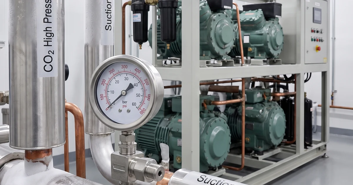
CO2 transcritical refrigeration pressure gauge selection means choosing local pressure indicators, transmitters and accessories for an R744 refrigeration rack whose high side may operate far above traditional HFC systems. The useful reading may be compressor suction pressure, discharge pressure, gas-cooler outlet pressure, flash-tank pressure or filter pressure loss. This guide explains where gauges belong, how to think about range and safety case selection, what materials should be confirmed, and what a pressure reading cannot prove without temperature, control and OEM rack data.
What CO2 transcritical refrigeration pressure gauge selection has to measure
CO2 transcritical refrigeration pressure gauge selection starts with the rack function, not only the dial range. R744 systems can include compressor suction, compressor discharge, gas cooler outlet, high-pressure valve inlet, flash tank, liquid header, evaporator branch and service filter points. Each point answers a different question.
ASHRAE publishes refrigeration safety guidance for carbon dioxide systems, including design-pressure logic for R744 circuits; see the ASHRAE Standard 15 addendum on carbon dioxide refrigeration systems. OEM rack manuals may use different pressure classes for low-temperature suction, medium-temperature suction, flash tank, liquid and high side sections, so final gauge selection must follow the project documents.
Local mechanical gauges help technicians confirm service conditions during walkdowns. Pressure transmitters are used where the value drives high-pressure control, compressor staging, alarm logic, trend records or safety shutdowns. A gauge should support the control system; it should not replace the rack controller, relief devices or commissioning procedure.
Review Stainless Steel Gauge OptionsExplore 143+ industrial gauge models→Typical measurement points on an R744 rack
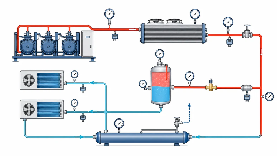
The same CO2 rack may need several pressure ranges because the suction side, receiver and high side operate in different windows. Treat each point as a separate service, then standardize only where the pressure class and diagnostic purpose are truly similar.
| Measurement point | Why technicians read it | Instrument choice |
|---|---|---|
| Compressor suction header | Evaporator load, starvation, valve behavior, low-pressure alarms | Gauge plus transmitter where control uses the value |
| Compressor discharge | High-side stress, gas cooler performance and abnormal restriction | High-pressure gauge or transmitter rated for the section |
| Gas cooler outlet / high-pressure valve inlet | Transcritical control and pressure optimization | Transmitter for control, local gauge for service confirmation |
| Flash tank / receiver | Liquid supply stability and bypass behavior | Gauge or transmitter matched to receiver design pressure |
| Filter drier or service filter | Restriction and contamination trend | Gauge pair or differential pressure method |
For adjacent topics, compare the A2L R-454B refrigerant pressure gauge selection guide and the ammonia refrigeration pressure monitoring guide.
Saturation pressure drives the range: standstill, off-cycle and the transcritical limit
The reason R744 gauge ranges look unfamiliar to engineers coming from HFC systems is thermodynamic rather than commercial. Carbon dioxide has a high saturation pressure at ordinary ambient temperatures, and its critical point sits at about 31.0 °C and 73.8 bar absolute. A rack that stops on a warm day drifts toward the saturation pressure of its own ambient temperature, which is why standstill and off-cycle pressure - not running pressure - so often sets the design pressure of the low side and the receiver.
| Temperature | CO2 saturation pressure (bar absolute, approx.) | Approx. gauge pressure | Why it matters |
|---|---|---|---|
| -40 °C | 10.0 | 9.0 barg | LT evaporating range on a typical supermarket rack |
| -30 °C | 14.3 | 13.3 barg | LT suction band |
| -20 °C | 19.7 | 18.7 barg | Low end of MT service on some systems |
| -10 °C | 26.5 | 25.5 barg | MT evaporating range |
| 0 °C | 34.9 | 33.9 barg | Flash tank and receiver band on many racks |
| 10 °C | 45.0 | 44.0 barg | Cool-ambient standstill |
| 20 °C | 57.3 | 56.3 barg | Room-temperature standstill; already above most HFC high sides |
| 30 °C | 72.1 | 71.1 barg | Warm standstill, just below the critical point |
These are rounded saturation values for pure CO2 from standard thermodynamic tables, given as a sense of scale. The design pressure and MAWP for each section come from the rack OEM documentation, not from this table, and a rack fitted with a standstill unit or a pressure-relief arrangement will behave differently from one that simply drifts to ambient.
Above the critical point there is no saturation temperature at all. On the high side of a transcritical rack, pressure and temperature become independent variables, which is exactly why the gas cooler outlet needs both a pressure measurement and a temperature measurement before the high-pressure valve position means anything. A technician who converts high-side pressure into a 'condensing temperature' the way they would on an HFC system is reading a number that does not exist in that operating region.
Prepare a CO2 Refrigeration Gauge RFQOur engineers respond within 24 hours→Range and case design for CO2 transcritical refrigeration pressure gauge selection
Range selection should begin with the rack pressure class, normal operating pressure, maximum expected pressure, relief settings, warm-standstill exposure and service-test procedure. Many CO2 sections require much higher pressure ratings than familiar HFC refrigeration points. Do not select a gauge only because the normal operating pressure fits the printed scale.
A readable dial normally places the routine reading away from the bottom stop and away from full scale. However, high-side CO2 service may prioritize overpressure margin and case safety over a narrow display range. If the medium is high-pressure gas near technicians, review whether a solid-front safety case with rear relief, laminated safety glass, stainless case and unobstructed blow-out clearance are required.
Pointer flutter can occur near compressors and valve stations. Liquid filling, movement damping, snubbers or remote mounting may improve readability, but they do not correct a wrong pressure class. See the pressure gauge snubber selection guide for pulsation logic.
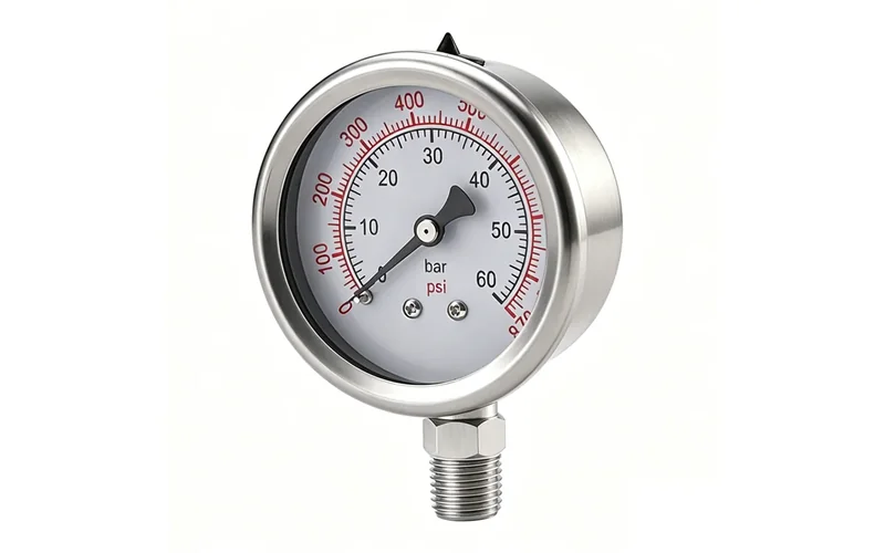
Materials, threads and installation details
CO2 is usually dry and non-corrosive in properly maintained refrigeration service, but the installation still needs careful material selection. Stainless steel wetted parts are a conservative default for industrial racks, outdoor units, washdown areas and systems where moisture, oil, cleaning chemicals or mixed service may occur. Brass may appear on some refrigeration service tools, but it should not be assumed suitable for every CO2 rack pressure class or customer standard.
Confirm connection standard, sealing method and access. Common refrigeration service connections are not the same as NPT, BSP, G or metric process threads. A near-fit thread is not a safe seal, especially on high-pressure gas. Gauge valves, service ports and capillary lines should be supported against vibration and placed where technicians can isolate and replace the instrument without bending small tubing.
For material reasoning, review 316L stainless steel vs brass pressure gauge wetted parts. The final material decision should follow the rack OEM, refrigerant/oil compatibility, customer specification and local code.
Unit, scale and range traps that cause wrong R744 orders
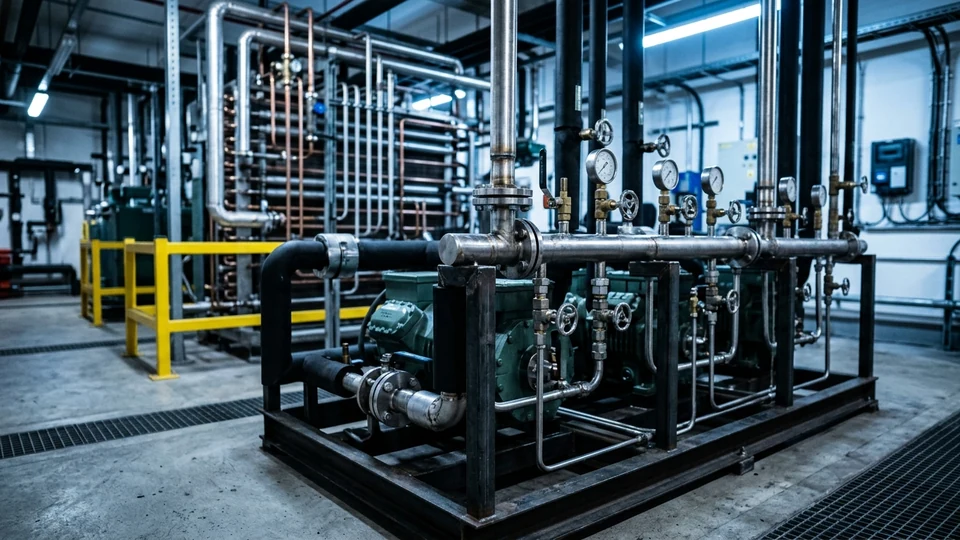
Most disputed CO2 gauge orders are not caused by a difficult specification. They are caused by a small number of repeatable ambiguities in how the request was written. Screening for them before the RFQ leaves the desk removes most of the rework.
| Trap | How it shows up | Prevention |
|---|---|---|
| Gauge pressure and absolute pressure mixed | A design figure quoted in bar absolute is ordered as a bar gauge scale, or the reverse | State barg or bara explicitly on every pressure in the RFQ and on the drawing |
| Unit mismatch between documents | OEM table in bar, site standard in MPa, distributor quote in psi | Fix one primary unit for the order and state any dual scale as a separate requirement |
| 'A CO2 gauge' ordered without the section | One range quoted for a rack that has LT suction, MT suction, receiver and high side | Name the section for every line item; attach the OEM pressure table |
| Range chosen from running pressure | Dial fits the duty point but is exceeded at standstill or during service testing | Size from MAWP and standstill pressure, then check the duty point falls mid-scale |
| Refrigeration service thread assumed to be a process thread | Ordered as NPT or G and the part does not seal on the rack | Quote the exact connection standard and supply a drawing of the mating part |
| HFC-range gauge reused during a retrofit | Existing dial looks similar and is refitted on a higher-pressure section | Re-derive the range from the R744 section data; do not carry over the old part number |
| Safety case not specified where exposure justifies it | Standard case fitted at a high-pressure point close to operators | Decide solid-front and rear-relief requirements from the risk assessment, and state it |
| No traceability requested | Gauges arrive without serials or certificates and cannot support handover records | State calibration certificate, serial marking and as-found data requirements in the order |
Worked range example. A section with an MAWP of 60 barg and a normal running pressure of 38 barg. A 0-100 bar dial puts normal running at 38% of span and MAWP at 60%, leaving margin above the highest credible pressure. A 0-60 bar dial places MAWP exactly at full scale with no margin at all, which is not a usable selection even though the number appears to match. Where operators stand close to a high-pressure point, review case design against the solid-front safety case selection guide and the pressure gauge overpressure protection guide.
What pressure readings cannot prove in a CO2 rack
A pressure reading cannot prove rack efficiency by itself. CO2 transcritical performance depends on gas cooler outlet temperature, ambient condition, compressor speed, high-pressure valve position, flash-gas bypass, evaporator load, refrigerant charge, oil management and controller strategy. A normal pressure value can still coexist with poor superheat control, fouled heat exchangers, sensor drift or incorrect commissioning parameters.
Pressure also cannot prove safety compliance alone. Relief valves, pressure vessels, piping design pressure, ventilation, leak detection, electrical classification where applicable and maintenance procedure must be reviewed separately. The gauge is an indicator, not an overpressure protection device.
For procurement language, avoid promising that CO2 transcritical refrigeration pressure gauge selection solves high-side control or refrigeration efficiency. It supports maintenance, troubleshooting and independent service confirmation when interpreted with temperature, controller and OEM data.
RFQ checklist for CO2 refrigeration pressure gauges
A complete RFQ should describe the exact rack section, not only the refrigerant name. Include medium as R744 / CO2, normal pressure, maximum pressure, design pressure or MAWP for the section, pressure unit, dial diameter, connection thread, bottom or back mount, wetted material, case type, window material, fill fluid, vibration exposure, ambient temperature, service valve arrangement and documentation needs.
- State whether the point is suction, discharge, gas cooler, receiver, liquid line, filter or service manifold.
- Confirm whether a mechanical gauge, pressure transmitter or both are required.
- Specify if the gauge must be stainless steel, liquid-filled, solid-front, oxygen-cleaned or supplied with a calibration certificate.
- Attach the rack OEM pressure table when available; do not ask suppliers to infer pressure class from the word CO2.
- For Manogauge OEM supply from Zhejiang, China, request a drawing, material statement, packaging requirement and sample approval record before bulk order.
This makes the quote safer and easier to compare than a generic request for a CO2 gauge.
Key takeaways
- CO2 transcritical refrigeration pressure gauge selection should be done by rack section: suction, discharge, gas cooler, flash tank, liquid line or filter.
- Standstill and off-cycle saturation pressure, not the running duty point, often sets the design pressure of the low side and receiver, so it must drive range and overpressure selection.
- Above the critical point there is no saturation temperature, so high-side pressure alone cannot be read as a condensing temperature; pressure and temperature are independent there.
- Pressure readings support service checks, but they do not prove efficiency, charge, relief protection or safety compliance by themselves.
Related buyer pages
Refrigerant pressure gauge supplierR744 high-side ranges reach 120-160 bar; confirm range and safety pattern before ordering.
Stainless steel pressure gauge manufacturerStainless wetted parts and cases for CO2 racks in humid machine rooms.
Liquid-filled pressure gauge supplierFilled gauges for compressor discharge vibration on transcritical racks.
Related reading
- Ammonia Refrigeration Pressure Gauge: R717 Materials and Safety
Ammonia refrigeration pressure gauge guide for R717 cold storage: suction, discharge, oil, defrost ranges, material compatibility and safety checks.
- Chiller Refrigerant High & Low Pressure Gauges: Selection Guide
Pick chiller refrigerant high pressure gauges and low-side compound gauges for R-134a, R-410A, R-407C and CO2: ranges, tube materials, connections and an RFQ checklist.
- 316L vs Brass Pressure Gauge Wetted Parts: Corrosion Guide
316L vs brass pressure gauge wetted parts compared for corrosion risk in water, steam, ammonia, seawater, chlorides, CIP/SIP cleaning and diaphragm seals.
- Compressed Air Pressure Gauge Selection Guide (bar & psi)
Pick compressed air pressure gauges from compressor room to point of use: bar/psi range, accuracy class, filter pressure drop, moisture, and an RFQ checklist.
- Pressure Gauge Factory Acceptance Test Checklist
Pressure gauge factory acceptance test checklist: inspection points, calibration evidence, leak checks, materials and the documents to demand before shipment.
Frequently asked questions
What pressure range is best for a CO2 transcritical refrigeration gauge?
There is no single range for the whole rack. Select by section pressure class, normal operating pressure, maximum expected pressure, relief setting and OEM data. Suction, receiver and high-side points often need different ranges.
Should a CO2 refrigeration gauge use a solid-front safety case?
Use a solid-front case where the risk assessment, pressure class, gas service and operator exposure justify it. High-pressure R744 points near technicians deserve special review of case design and rear relief clearance.
Can a standard refrigerant manifold gauge be used on an R744 rack?
Only if its pressure rating, connection, material and service procedure match that exact point. CO2 rack sections can exceed familiar refrigerant service-tool assumptions.
Are stainless steel wetted parts required for CO2?
Dry CO2 is not usually corrosive, but stainless steel is often the conservative choice for industrial racks, outdoor service, washdown areas and customer standards. Confirm with OEM and project specification.
Can pressure readings prove CO2 rack efficiency?
No. Efficiency needs pressure plus temperature, controller state, gas cooler data, compressor operation, charge, oil management and OEM performance logic.
What is CO2 standstill pressure and why does it matter for gauge range?
When an R744 system stops, the refrigerant warms toward ambient and its pressure rises toward the saturation pressure at that temperature - roughly 57 bar absolute at 20 degrees C and about 72 bar absolute at 30 degrees C. That standstill pressure, not the running pressure, often sets the design pressure of the low side and receiver, so gauge range and overpressure rating must cover it. The actual figures for a given rack come from the OEM, especially where a standstill unit or relief arrangement is fitted.
Is there a saturation temperature on the high side of a transcritical rack?
Not above the critical point, which for CO2 is about 31.0 degrees C and 73.8 bar absolute. In transcritical operation pressure and temperature are independent, so gas cooler outlet pressure cannot be converted into a condensing temperature the way it can on an HFC system. That is why the gas cooler outlet needs both a pressure and a temperature measurement before the high-pressure valve position can be judged.
Should CO2 refrigeration gauges be marked in bar gauge or bar absolute?
Whichever the project standard specifies - but it must be stated explicitly, on both the RFQ and the drawing. Mixing an absolute design figure with a gauge-marked dial is one of the most common causes of a wrong R744 gauge order, and the difference of roughly one bar is significant at low-temperature suction points where the whole operating band is narrow.