Vacuum pressure gauge selection follows a different logic from positive-pressure selection, and the differences are easy to miss because the instrument looks the same. The scale runs the wrong way, the span ends at atmospheric pressure instead of starting there, the medium may boil rather than compress, and the resolution a mechanical dial can deliver runs out long before the vacuum levels that process engineers care about. This guide sets out the four pressure references and how to read them, matches vacuum levels to sensing elements using the ISO 3529 classification, shows how to split the range on a compound gauge, and states plainly where a mechanical vacuum gauge has to hand over to an electronic instrument.
What a vacuum gauge measures, and why it is not a pressure gauge reversed
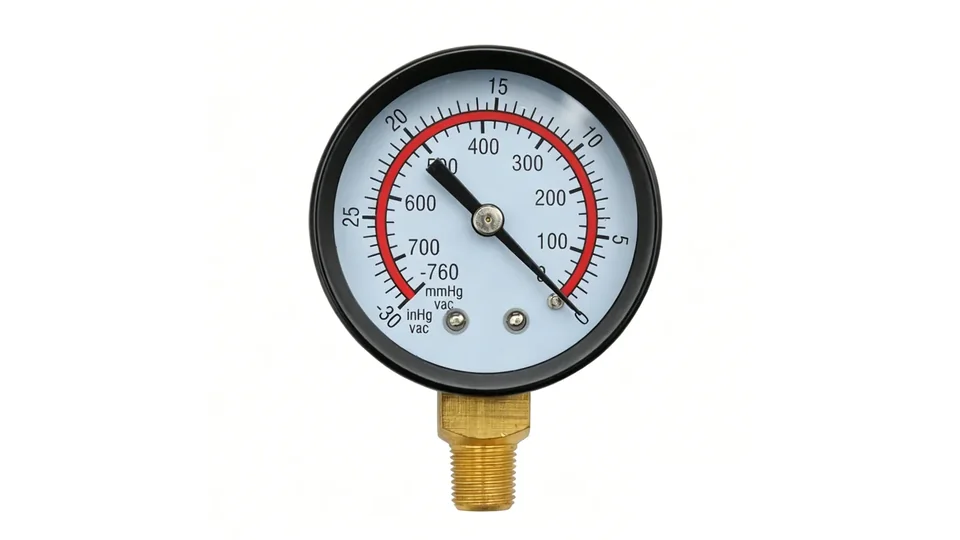
A vacuum gauge is an instrument whose scale reads below ambient atmospheric pressure. Like an ordinary pressure gauge it measures relative to atmosphere, so its scale runs from 0 down to a theoretical minimum of −1 bar, the point at which the process side contains nothing at all. That single sentence contains the three differences that drive selection.
- The span is fixed at one end. A positive-pressure gauge can be specified with any full scale; a pure vacuum gauge always ends at −1 bar (−1000 mbar, −760 mmHg, −29.92 inHg), because atmospheric pressure is the largest differential available. You cannot buy more span to improve resolution.
- The failure mode changes. Overpressure bursts an elastic element outwards; vacuum pulls it the other way, and a bourdon tube sized for a positive range is comparatively weak in that direction. Repeated full-vacuum excursions on a gauge not rated for them cause permanent zero shift long before any visible damage.
- The medium can change state. Lowering the pressure lowers the boiling point. Liquids that are perfectly stable at 1 bar will flash to vapour in the connection line under vacuum, and vapours will condense back to liquid in a cold line. Neither happens on the positive side of the same process.
Selection therefore starts with a question that never arises for positive pressure: how deep does the vacuum actually go, and is a mechanical dial able to resolve it?
Browse Vacuum and Compound Gauge RangesExplore 143+ industrial gauge models→Four pressure references on one table
Most vacuum specification errors are reference errors — the number is right and the datum is wrong. Four references are in daily use, and a compound gauge sits across two of them.
| Reference | Zero point | Typical scale | Reads at full vacuum | Used for |
|---|---|---|---|---|
| Gauge pressure | Ambient atmosphere | 0 to +N bar | n/a | Ordinary positive-pressure service |
| Vacuum (negative gauge) | Ambient atmosphere | −1 to 0 bar, or 0 to −1000 mbar | −1 bar | Suction lines, vacuum pumps, holding systems |
| Compound | Ambient atmosphere | −1 to 0 to +N bar | −1 bar | Processes that cross atmosphere in both directions |
| Absolute | Perfect vacuum | 0 to N bar a / mbar a | 0 bar a | Boiling point control, freeze drying, altitude-independent readings |
The conversion that resolves most disputes: absolute pressure = gauge pressure + ambient atmospheric pressure, with the standard atmosphere taken as 1013.25 mbar. A vacuum gauge reading −0.8 bar is therefore at roughly 213 mbar absolute; a distillation column specified at 100 mbar absolute is at about −0.91 bar on a vacuum dial.
The practical difference between vacuum and absolute is the datum's stability. A vacuum gauge is referenced to the atmosphere around it, so its reading moves with the weather and with site elevation — at 1500 m the same physical condition reads several tens of millibars differently. Where the process is controlled by the boiling point of a liquid, that datum drift is unacceptable and an absolute instrument is the correct specification, not a vacuum gauge with an offset applied.
Vacuum levels and the sensing element that matches them
Vacuum is classified by decade, most commonly following the ISO 3529 / DIN 28400 convention. Elastic elements — bourdon tubes, capsules, diaphragms — measure a force produced by a pressure difference, and that force disappears as the absolute pressure approaches zero. This is a physical ceiling, not a quality issue: the choice of element and the choice of technology are the same decision.
| Vacuum level | Absolute pressure | Suitable measurement | Typical application |
|---|---|---|---|
| Rough (low) vacuum | 1000 to 1 mbar | Bourdon tube for the upper part of the decade; capsule or diaphragm element where the last 100 mbar must be readable | Pump suction, vacuum conveying, filling and packaging, vacuum lifting, refrigerant evacuation down to the coarse stage |
| Medium (fine) vacuum | 1 to 10⁻³ mbar | Electronic: Pirani / thermal conductivity, capacitance manometer | Freeze drying, vacuum drying, degassing, coating pre-pumping |
| High vacuum | 10⁻³ to 10⁻⁷ mbar | Ionisation gauges | Thin-film deposition, analytical instruments |
| Ultra-high vacuum | below 10⁻⁷ mbar | Specialised ionisation gauges | Research, semiconductor process chambers |
Mechanical dial instruments therefore serve the rough vacuum decade and nothing below it. Within that decade the element still matters. A bourdon tube is stiff and gives a usable indication over the −1 to 0 bar span, but it has little sensitivity in the last stretch toward full vacuum. A capsule element — two corrugated diaphragms welded at the rim, deflecting under a small differential — has far more travel per millibar and is the correct choice when a scale such as 0 to −600 mbar or a range in mbar has to be read meaningfully. Where the medium is aggressive or laden with particles, a diaphragm or diaphragm-seal construction takes over for reasons of material rather than sensitivity.
Compare Bourdon, Diaphragm and Capsule Elements→Selecting a compound gauge: how to split the range
A compound gauge reads on both sides of atmospheric pressure, which is what a process needs when it is evacuated and then pressurised, or when a suction line can go positive on shutdown. The negative side is fixed at −1 bar. Only the positive side is a choice, and it is made exactly as it would be for a positive-pressure gauge: take the maximum credible pressure, apply the sizing rule from pressure gauge range calculation, and round up to a standard range.
The consequence engineers underestimate is what the positive side does to the vacuum side. Accuracy class is a percentage of the whole span, and on a compound gauge the span includes the 1 bar of vacuum. Compare two instruments watching the same −0.8 bar suction condition:
| Gauge | Total span | Permitted error, class 1.6 | Error at a −0.8 bar reading |
|---|---|---|---|
| −1 to 0 bar vacuum | 1 bar | ±0.016 bar | ±2% |
| −1 to +3 bar compound | 4 bar | ±0.064 bar | ±8% |
| −1 to +24 bar compound | 25 bar | ±0.40 bar | ±50% |
A −1/+24 bar compound gauge is a perfectly good instrument for confirming that a system has been pulled down and then charged. It is not an instrument for controlling a vacuum level, because its error at −0.8 bar is half the reading and its scale gives roughly 4% of the dial arc to the entire vacuum range. The rule that falls out of the table: the wider the positive side, the coarser the vacuum side becomes. Where both a deep vacuum and a high positive pressure must be measured accurately, the answer is two instruments, not one wide compound dial. Refer to the accuracy class selection guide for how to convert the class into the error at your working point.
Medium behaviour under vacuum
Reducing pressure reduces boiling point, and the connection to a vacuum gauge is usually the coldest, deadest part of the system. Three consequences show up repeatedly in service.
Vaporisation and condensation in the line
Water boils at roughly 45 °C at 100 mbar absolute and at about 7 °C at 10 mbar. In a vacuum drying or evaporation process, liquid carried into the impulse line will flash and then recondense in the cooler section, leaving a slug that damps the reading or blocks it entirely. Mount the instrument above the tapping point where the process is liquid-prone, keep the line short, and avoid pockets.
Solvent and process vapours
Vacuum service in chemical and pharmaceutical plants frequently means solvent vapour, which attacks elastomers and can permeate soldered joints. Where the vapour is aggressive or the process must stay uncontaminated, a diaphragm seal isolates the element behind a welded membrane, with the filling fluid selected for the temperature range and the process compatibility. Note the trade-off: a seal adds its own error and slows the response, so it should be specified for material reasons rather than by default.
Particulates and carry-over
Vacuum conveying, drying and filtration all move solids, and a bourdon tube packs with dust rather than plugging cleanly. Flush-diaphragm connections avoid the dead volume where solids collect; where a filter is fitted in the impulse line, remember that a partly blinded filter turns the gauge into a slow average and the reading will lag any real transient.
Temperature at the connection deserves the same attention as on the positive side. Vacuum drying, evaporation and clean-in-place systems all put hot media against instruments, and every degree away from the reference temperature adds error that the accuracy class does not include.
Case, safety pattern and mechanical limits
The safety patterns defined in EN 837-1 — including the solid-front case with a blow-out back — exist to direct the energy released when a pressure element fails under overpressure. They are specified from the positive side of a compound gauge, and they are not what protects an instrument in vacuum service. On the vacuum side, three different points matter:
- Confirm the gauge is rated for full vacuum. Not every positive-range instrument tolerates being pulled to −1 bar. A gauge used on a line that can go into vacuum on pump shutdown or during draining needs that condition on the datasheet, not assumed.
- Check the case vent on liquid-filled instruments. A filled case is sealed for transport and vented at commissioning through a compensating valve. If it is left sealed, ambient temperature changes and altitude shift the zero — a particularly confusing fault on a vacuum dial, where the entire span is only 1 bar and a small zero error is a large percentage.
- Respect the element's over-travel limit. A pointer that has been driven hard against the vacuum stop repeatedly will show a permanent zero offset. If the system routinely bottoms out the scale, the range or the element type is wrong.
Case material and ingress protection are chosen the same way as for any other duty: stainless steel where the ambient is corrosive or washed down, IP-rated enclosures outdoors, and liquid filling where the gauge is mounted on or near a running vacuum pump, which is one of the more vibration-heavy machines in a plant room.
Where vacuum and compound gauges are actually used
Four duties account for most industrial mechanical vacuum measurement, and each has a specification detail that is easy to miss.
Pump suction monitoring
A compound gauge on the suction side of a centrifugal pump, typically −1 to +1.5 bar or −1 to +3 bar, shows a clogged strainer, a closing suction valve or a falling supply level before cavitation damages the impeller. The instrument does not measure NPSH, which is a calculated margin above vapour pressure, but the trend it shows is the earliest visible symptom. See centrifugal pump gauge selection for how suction and discharge instruments are paired.
Refrigeration and HVAC service
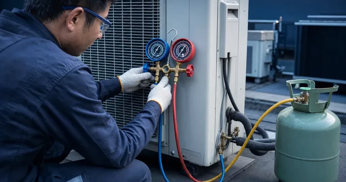
Manifold gauge sets use compound dials because the low-side line runs into vacuum during evacuation and into positive pressure during operation and charging. The compound dial confirms the pull-down has started and confirms the charge afterwards; it does not qualify the evacuation. Refrigerant work also constrains the wetted materials and the scale, since A2L refrigerants require pressure-temperature scales matched to the specific blend.
Vacuum drying, distillation and evaporation
Here the controlled variable is the boiling point, which depends on absolute pressure. A vacuum gauge referenced to the local atmosphere is acceptable for monitoring the pump, but the process instrument should be an absolute one, in mbar a, and usually electronic once the setpoint goes below about 50 mbar.
Vacuum handling, packaging and conveying
Lifting cups, vacuum conveyors and packaging machines run at a few hundred millibars below atmosphere. A capsule-element vacuum gauge in mbar is far more readable here than a −1 to 0 bar bourdon dial, because the whole working range occupies most of the scale rather than a third of it.
What a mechanical vacuum gauge cannot tell you
The boundaries below are the ones worth writing into a specification, because each has been the cause of an instrument being blamed for a process problem it was never able to see.
- It cannot qualify a deep evacuation. Refrigeration and pharmaceutical evacuation targets are quoted in microns of mercury: 500 microns is 0.667 mbar absolute, roughly −1.013 bar gauge. On a −1 to 0 bar dial with a 1 bar span, a class 1.6 instrument is permitted ±16 mbar — about twenty-four times the entire target. A thermistor or Pirani micron gauge is the correct instrument, and no dial size or accuracy class changes that.
- It cannot prove leak tightness. A steady pointer shows that the system is not losing vacuum fast enough to be visible at the instrument's resolution. Leak testing is a rate-of-rise or tracer-gas measurement.
- It cannot distinguish vacuum from absolute. Its datum moves with the weather and with site elevation. Where the process is a boiling point, use an absolute instrument.
- It cannot confirm medium compatibility, maximum credible pressure or the safety function of the loop. Wetted materials, the highest pressure the line can reach on failure, and any safety-related use must be confirmed by the engineer responsible for the process.
Used inside those limits, mechanical instruments are the right answer for the rough vacuum decade: they need no power, they survive plant-room conditions, and they show a trend at a glance. Manogauge builds vacuum and compound gauges across the −1 bar to +600 bar range in NS 50 to NS 160 dials, in bourdon and capsule elements, with steel and stainless cases, under an ISO 9001 quality system and to EN 837-1 dimensions and class limits. Sound vacuum pressure gauge selection comes down to three confirmed numbers — the deepest vacuum, the highest positive pressure, and the resolution the process actually needs at the working point — plus an honest decision about whether a dial can deliver it at all.
Key takeaways
- A vacuum gauge is referenced to atmosphere and ends at -1 bar, so its span is fixed; only a compound gauge's positive side is a free choice.
- Accuracy class applies to the whole span: a -1/+24 bar compound gauge in class 1.6 is ±0.4 bar, which is ±50% of a -0.8 bar reading.
- Mechanical dials serve the rough vacuum decade (1000 to 1 mbar); below 1 mbar absolute a Pirani or capacitance instrument is required.
- A 500 micron evacuation target is 0.667 mbar absolute — roughly twenty-four times finer than a class 1.6 vacuum dial can resolve, so use a micron gauge.
- Under vacuum the medium can vaporise or condense in the impulse line; mounting position, diaphragm seals and particulate protection matter more than on the positive side.
Related reading
- Pressure Gauge Accuracy Class Selection: 4 Key Variables
Pressure gauge accuracy class selection: what EN 837-1 classes permit, how span and working point change the real error, and which class each duty needs.
- Fire Sprinkler Pressure Gauge Requirements: UL 393, NFPA 25
Fire sprinkler pressure gauge requirements: why NFPA 13 wants a UL 393 listed or FM Approved gauge, how to pick range, and NFPA 25 replacement rules.
- How to Calculate Pressure Gauge Range: 75% Rule and Examples
Calculate pressure gauge range step by step: divide maximum pressure by 0.75 or 0.65, round up to a standard range, then check the working point and accuracy.
- Chiller Refrigerant High & Low Pressure Gauges: Selection Guide
Pick chiller refrigerant high pressure gauges and low-side compound gauges for R-134a, R-410A, R-407C and CO2: ranges, tube materials, connections and an RFQ checklist.
Frequently asked questions
When should an HVAC engineer use a compound gauge and when a separate vacuum gauge?
Use a compound gauge wherever the line crosses atmospheric pressure in normal operation — a refrigeration low side that is evacuated during service and positive when running, or a pump suction that can go positive on shutdown. Use a dedicated vacuum instrument when the vacuum level itself is the controlled variable, because a compound dial gives the whole vacuum range only a small fraction of the scale arc and its class error, calculated on the full span, is often larger than the resolution you need.
Can a -1 to +24 bar compound gauge really measure down to -1 bar?
It reaches -1 bar mechanically, but it cannot resolve there. The class error is calculated on the 25 bar total span, so a class 1.6 instrument is permitted ±0.4 bar anywhere on the dial — half the value at a -0.8 bar reading. The vacuum section also occupies only about 4% of the scale arc. Treat a wide compound gauge as confirmation that vacuum exists, and use a dedicated -1 to 0 bar or mbar instrument when the number matters.
What is the difference between a vacuum gauge and an absolute pressure gauge?
A vacuum gauge is referenced to the ambient atmosphere and reads 0 at atmospheric pressure and -1 bar at full vacuum. An absolute gauge is referenced to perfect vacuum and reads about 1013 mbar a at sea level and 0 at full vacuum. Because a vacuum gauge's datum moves with the weather and with site elevation, processes controlled by boiling point — distillation, freeze drying, evaporation — should be specified in mbar absolute rather than as a vacuum reading with a correction applied.
Why does a pump suction line need a vacuum or compound gauge?
The suction side runs below atmospheric pressure whenever the pump lifts from a lower level or draws through a restriction, and a positive-range gauge simply sits on its stop and shows nothing. A compound gauge in the -1 to +1.5 bar or -1 to +3 bar range makes a blocked strainer, a throttled suction valve or a falling supply level visible as a trend, which is the earliest practical warning of cavitation. It does not measure NPSH available, which has to be calculated from the vapour pressure of the liquid at its actual temperature.
Can an ordinary compound gauge verify a micron-level refrigerant evacuation?
No. Evacuation targets are quoted in microns of mercury, where 500 microns equals 0.667 mbar absolute or about -1.013 bar gauge. A -1 to 0 bar dial has a 1 bar span, so even class 1.6 allows ±16 mbar of error — around twenty-four times the whole target value. The compound gauge on a manifold set shows that the pull-down is under way; a thermistor or Pirani micron gauge is what qualifies the result, and a rate-of-rise check is what confirms the system holds.
Which sensing element suits a millibar vacuum range?
A capsule element. It is built from two corrugated diaphragms welded at the rim and deflects far more per millibar than a bourdon tube, so it gives a readable scale for ranges such as 0 to -600 mbar or 0 to -1000 mbar. A bourdon tube is stiff and is the right choice when the same instrument must also carry a substantial positive range. Where the medium is corrosive, viscous or carries particles, the decision is driven by wetted materials instead, and a diaphragm or diaphragm-seal construction takes over.